Larson Engineering & Design, Kenai, Alaska

Engineering for Alaska's oilfield, offshore, and remote sites.

  • 900+ projects engineered since 2011
  • 1,000+ parts in a typical 3D model, with clearances checked before steel is cut
  • FEA on lifting eyes, ice breaker walls, rig hold-downs, and padeyes
  • Next door Ridgeline fabricates most LED designs, so drawings are built by the people who wrote them

Services

Stamped structural and civil engineering for the people who build and run industrial sites in Alaska: operators, drilling contractors, fabricators, general contractors, and local owners.

Offshore and platform modifications

Deck framing, conductor slots, catwalks, stairs, crane pedestals, ice breakers, and P&A support for Cook Inlet platforms.

Drilling rig equipment

Mud systems, BOP handling, rig hold-downs, man riders, transport skids, and rig-up planning.

Lifting and handling

Spreader bars, padeyes, helicopter baskets, lift plans, trolley beams, jib and bridge cranes, and load tests.

Facility and skid design

North Slope skids, platforms, shelters, containments, pipe racks, and module reviews.

Laser scanning and as-builts

Existing-conditions scans, scan-to-model, as-built drawings, and clash checks.

Bridges

Temporary construction bridges, pedestrian bridges, load rating, and inspection.

Buildings and foundations

Hangars, shops, additions, mezzanines, and seismic evaluations.

Civil and site

Roads, drainage, paving, subdivisions, and water and sewer around the Kenai Peninsula.

Wastewater and soils

Septic design and certification, perc tests, and soils reports.

Inspection and compliance

Special inspection, structural condition surveys, SPCC plans, and floodplain no-rise studies.
Projects

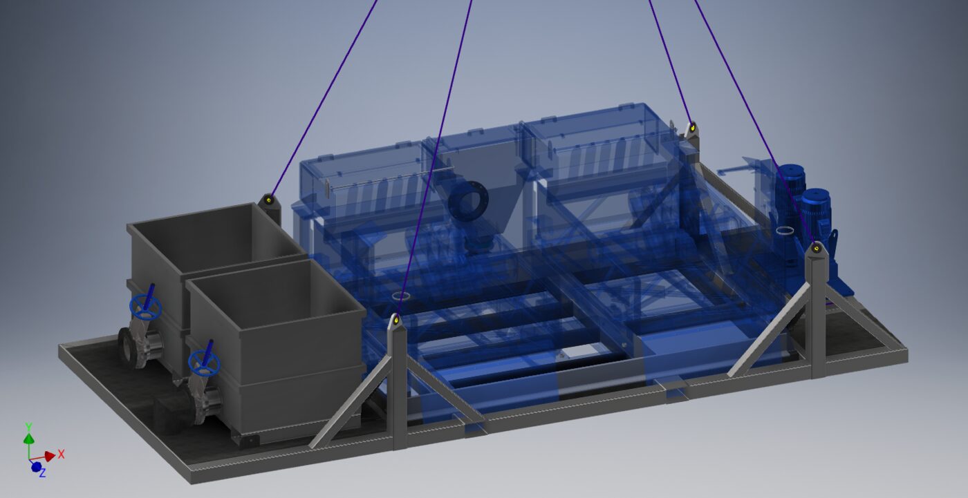
3D model of a rig mud system skid rigged for a crane lift

Flagship, oilfield

Remote exploration drilling rig

A one-of-a-kind rig headed to a roadless site, reached only by barge and helicopter. LED engineered the site layout and a very large share of the steel around the rig.
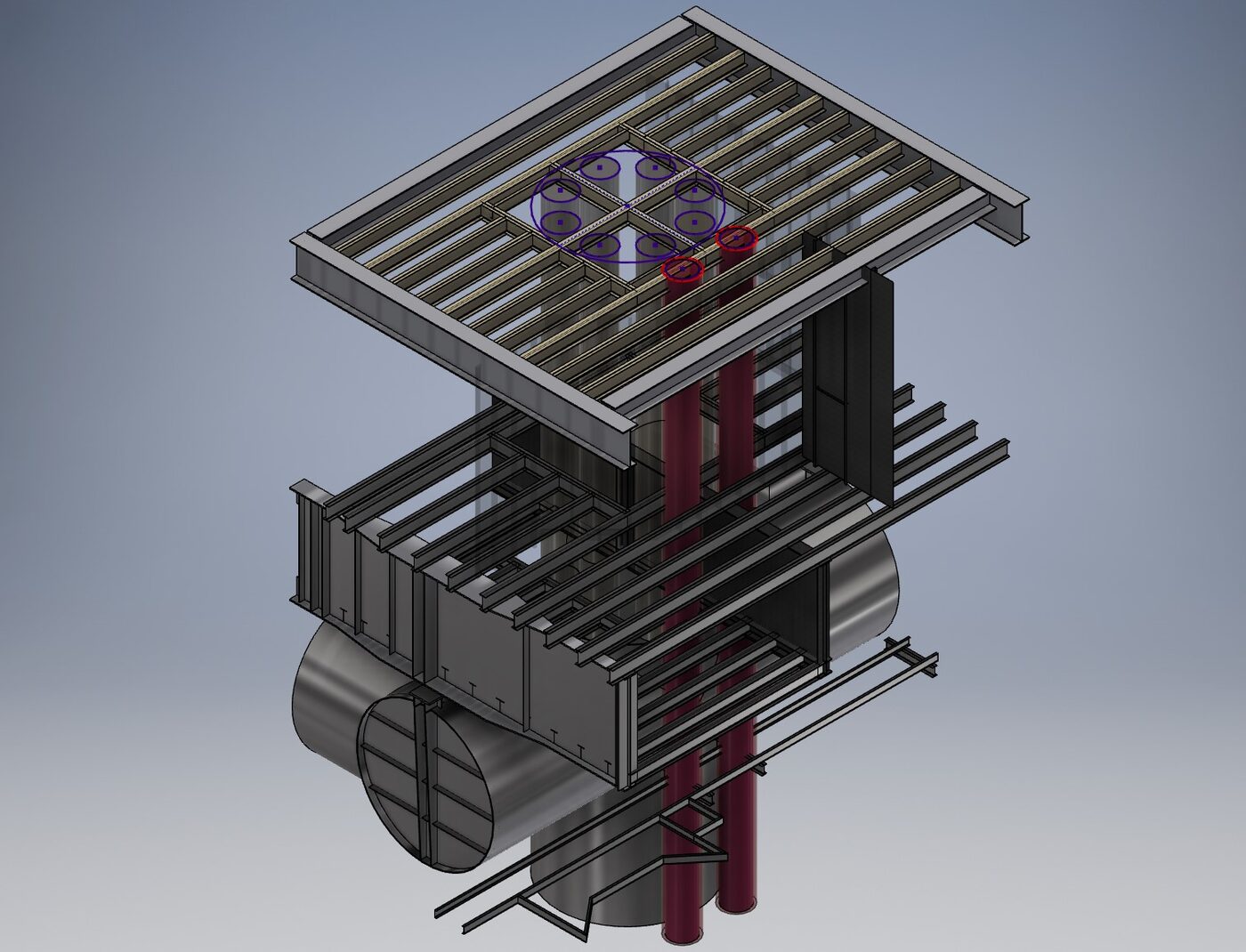
3D model of platform deck framing with conductor pipes passing through the new slots

Offshore

New conductor slots on an offshore platform

Well slots through every deck of a Cook Inlet platform leg, designed from laser scan data.
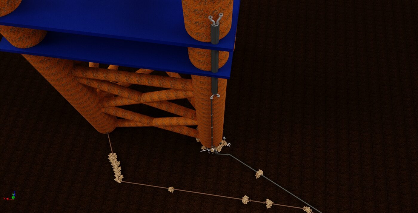
3D model of an offshore platform leg with a riser and subsea pipelines

Offshore

Platform leg ice breakers

A 60 ft steel shell that protects risers from Cook Inlet sea ice, adapted for multiple legs.
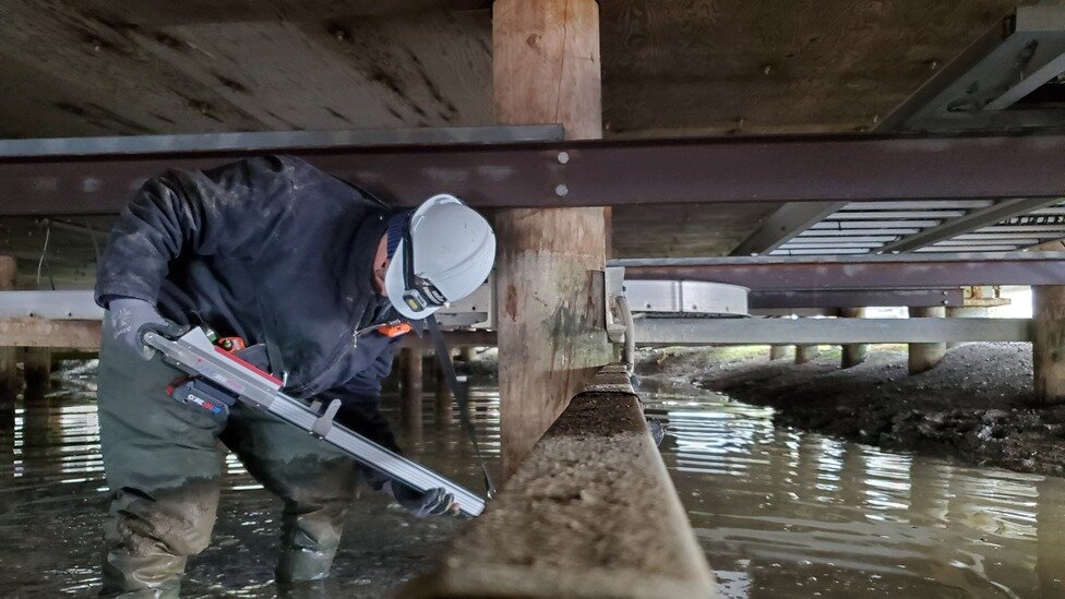
Inspector using a resistance drill on a timber pile under a facility module

North Slope, inspection

Timber pile inspection and repair

1,146 piles surveyed, 14 repaired in 7 working days, and a plan for next season.
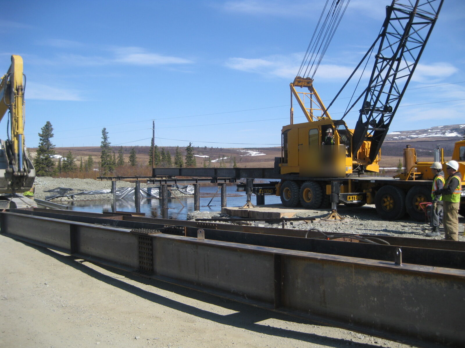
Steel beams staged beside a creek while a crane sets a temporary bridge

Bridges

Temporary highway bridges

Bridges that carry live traffic while a contractor replaces the permanent one. Done repeatedly since 2011.
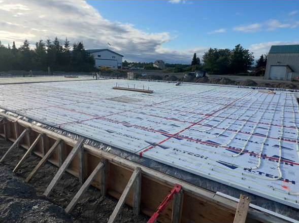
Insulated hangar foundation slab with radiant tubing laid out inside wood forms

Buildings

Hangar foundations at remote sites

Stamped foundations, site plans, and permit sets for pre-engineered hangars, from Kenai to Yap.

Sister company

Engineered here. Fabricated next door.

Ridgeline Oilfield Services is LED's sister company and fabrication shop. Most of what LED designs gets built there, so the people cutting the steel can walk over and talk to the people who drew it. Fewer RFIs, faster fixes, and a model that matches what shows up on the truck.

Visit Ridgeline
Mud system modules, fabricated and staged.

Laser scanning

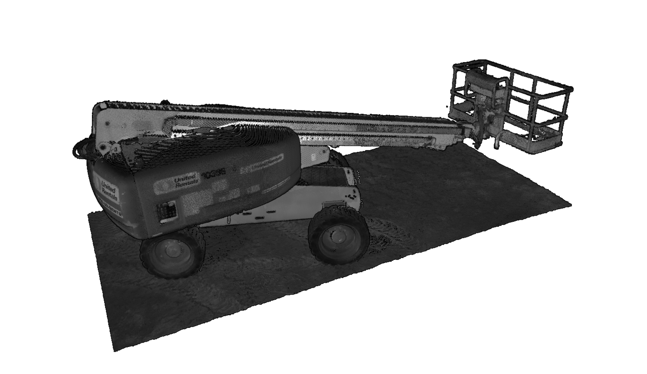
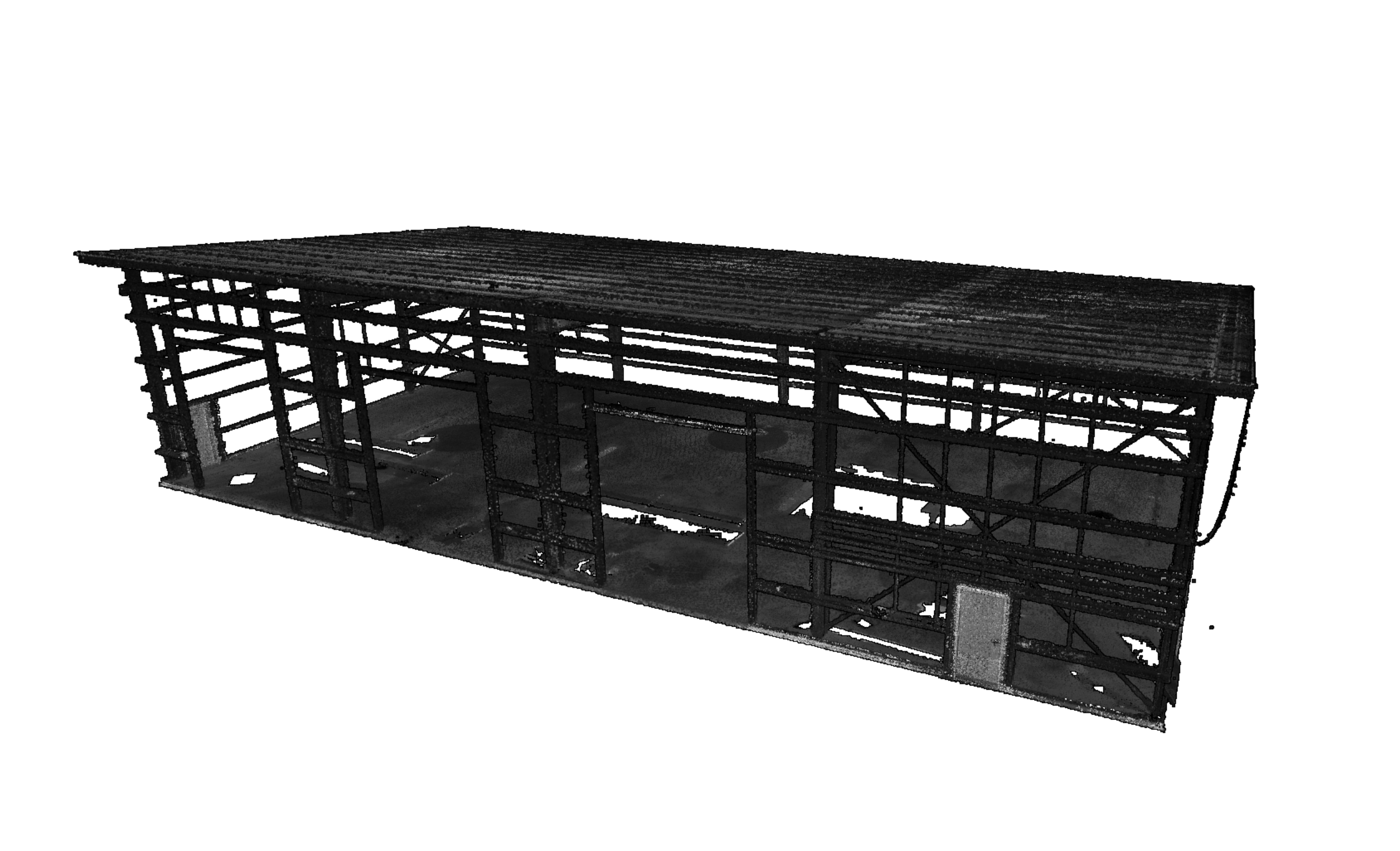
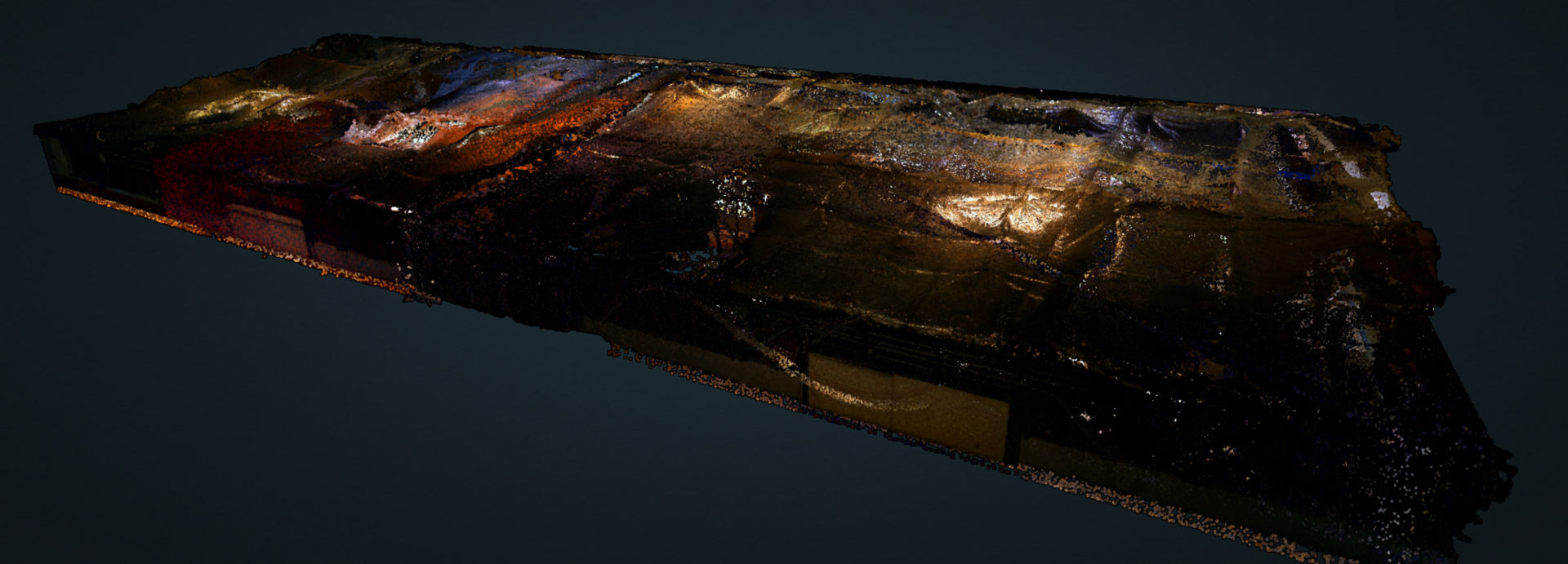
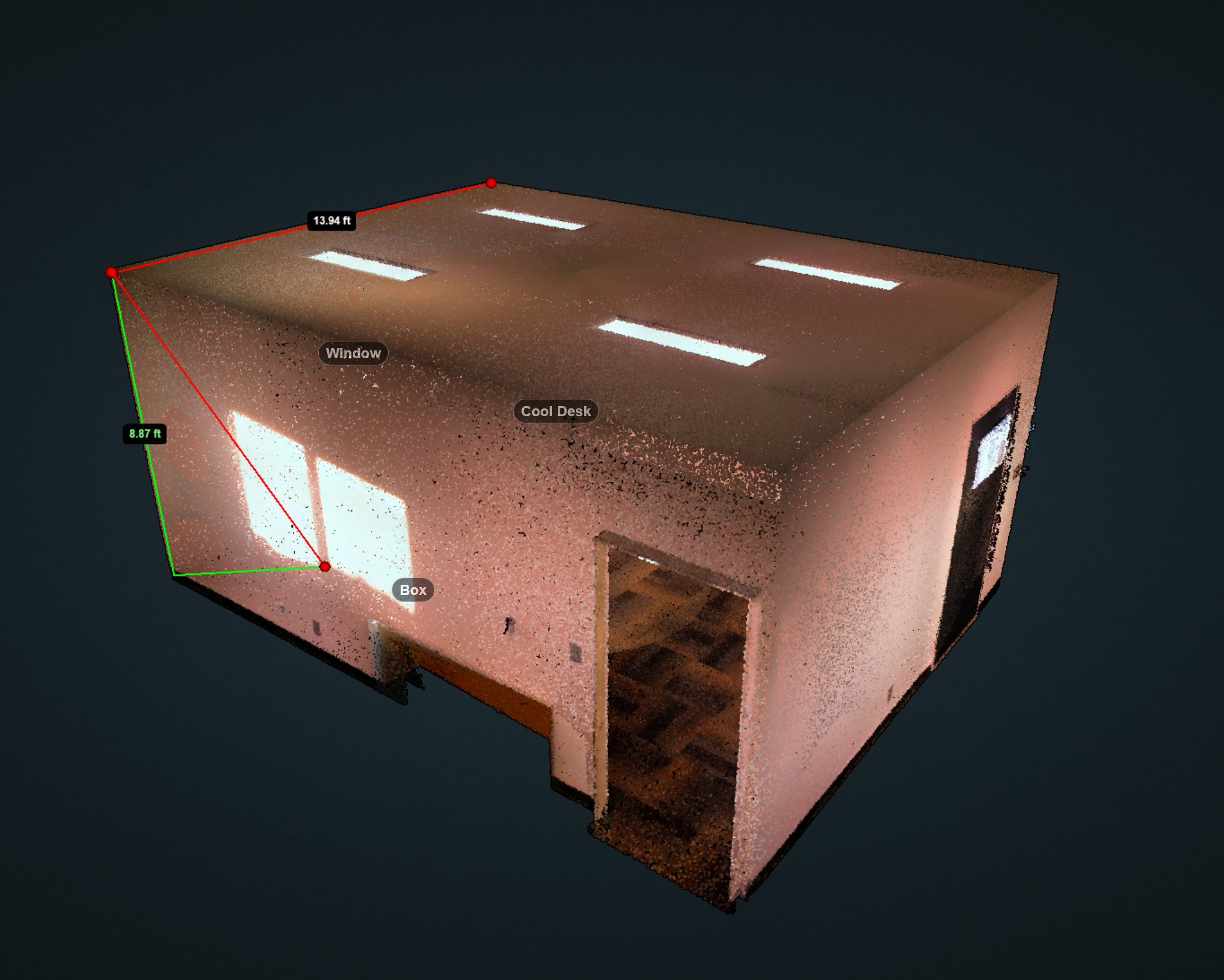
LED owns a Trimble laser scanner. From a broad site down to the smallest surface change, scans feed straight into the 3D model, so new steel fits the structure that is actually there.

This is a real scan of Larson Engineering offices.

From point cloud to stamped drawing

1

Scan

We capture existing conditions on site: a platform deck, a shop, a mezzanine, a piece of equipment.

2

Scan-to-model

The point cloud becomes a 3D Inventor model of the real structure, reconciled against any historical drawings.

3

Design and clash check

New work is designed in the model and checked for clearances before anything is fabricated, then issued as as-builts or construction drawings.

About LED

Larson Engineering and Design is a small structural and civil engineering firm in Kenai, Alaska. We have been issuing stamped drawings since 2011 and have engineered roughly 900 projects since, from offshore platforms in Cook Inlet to facilities on the North Slope.

Blake Larson, PE (structural and civil) is the head of the company and a licensed engineer himself. He is the engineer of record and stamps every set of drawings. Day-to-day projects are handled by LED's engineers and drafters, a team that includes a civil engineer, a mechanical technologies engineer, and three drafters, with Blake reviewing and certifying the work.

The work is modeled in 3D in Autodesk Inventor, checked with FEA, and in most cases fabricated next door at Ridgeline. Alaska conditions are the design basis, not an afterthought: ice loading, service temperatures down to -60°F, permafrost foundations, and helicopter and barge logistics.

Contact Us

Location

53510 Veco Ave, Kenai, AK 99611

Hours

Mon-Fri 8:00 AM - 4:00 PM

Have a platform modification, a lift, a skid, or a site that needs a second set of eyes? Send us the scope, even if it is rough. One of our engineers will read it and call you back.

Local owners with septic, soils, or floodplain questions are welcome too.

Email Us
Flagship, oilfield

Remote exploration drilling rig

3D model of a mud system skid rigged for a 40,000 lb crane lift

The problem

A one-of-a-kind drilling rig was headed to a remote exploration site with no road access. The rig came from a builder in Canada. Everything around it had to be engineered here, arrive by barge or helicopter, go together in the right order, and work the first time.

What LED did

Over about a year, from mid 2024 to mid 2025, LED modeled the full rig and site in 3D, then designed the equipment around it:

The same model produced a 45-step rig-up sequence used for crew onboarding.

The result

One coordinated model, issued-for-construction packages for each component, much of the steel fabricated next door at Ridgeline, and a rig crew that could see the assembly before it arrived on site.

By the numbers

Site and mat layout300 x 200 ft rig mat pad, barge landing, helicopter LZ, camp, two candidate pads compared
Mud tanks30 x 10.5 x 7 ft modules, 15,650 lb each, crane and helicopter lift plates, fork pockets, FRP grating
Diesel hammer lead skid20 ft lead on an outrigger base frame, FEA on the frame, renders and animation for client review
Barge ramps30 ft W14x43 ramps, 50,000 lb max center point load, interface to modular barge locks
Helicopter baskets12 ft and 18 ft aluminum baskets, swing gate, deck load FEA
Aluminum tanksTandem cement tanks with padeye FEA, aluminum fuel tanks
Rig componentsSuitcase skid, charge pump skid, suction strainers, HP piping, choke manifold, derrick stand, annular transport skid, heli-lift cuttings boxes
Rig-up sequence45-step assembly guide built from the model for crew onboarding
Side view of a mud system skid on a 40,000 lb lift with two-leg rigging

Mud system skid rigged for a 40,000 lb lift.

Offshore

New conductor slots on an offshore platform

3D model of platform deck framing with conductor pipes passing through the new slots

The problem

An operator wanted to drill new wells from an existing Cook Inlet production platform. The new conductors had to pass through the drill deck, sub deck, production deck, and spider deck of a structure whose drawings dated back decades.

What LED did

Working from laser scan data of the leg and decks, LED built the existing framing in 3D and reconciled it against the historical drawings. LED then designed the penetrations, framing reinforcement, new hatch covers, and relocated firewalls around it. The same model was used to design skid beam diaphragms so the platform crane could be skidded into place fully assembled, and to check clearances for the drilling rig moving aboard.

The result

A 22-sheet issued-for-construction package, from first review set to final revision in under three months.

By the numbers

ScopeNew conductor slots through drill, sub, production, and spider decks, firewalls, hatch covers, conductor sleeves
CraneSkid beam diaphragms with anti-racking bracing to skid an assembled crane, DXF output for cutting
ScheduleIssued for approval Jan 17, issued for construction Jan 29, Rev B Apr 10, 2025
Earlier work on the same platform2021 rig hold-downs with FEA and clearance studies, 2022 rig sockets, skybridge, and deck layouts, 2024 crane upgrades

Offshore

Platform leg ice breakers

3D model of an offshore platform leg with a riser and subsea pipelines

The problem

Cook Inlet ice loads platform legs on every tide, and the pipelines and J-tubes that run up those legs take the hits. An operator needed shields that could be fabricated onshore, handled from the platform deck, and grouted solid around existing legs.

What LED did

LED designed a 60 ft steel ice breaker shell that wraps the leg and protects the risers inside it, checked against 24 in sheet ice and 48 in rafted ice. Lifting eyes were sized with FEA, and wall stresses were checked for grout pressure during cure. To install it, LED designed a deck-mounted lifting frame with a hydraulic winch and snatch block, so the ice breaker could be handled from the platform itself.

The result

One design, adapted for multiple platform legs, each with its own riser and subsea constraints. Several are installed, with more designed and awaiting installation.

By the numbers

First design60 ft shell, 14-sheet drawing set, FEA for lifting stress and wall stress during grout cure, 12T and 4.75T lifting eyes
Second platformAdapted around two 10 in subsea pipeline tie-ins
Another legPipeline and J-tube protection. Ice force analysis: 537,600 lb crushing load against 2,664,000 lb weld capacity
Lifting system28 ft W12x58 lifting frame, hydraulic winch, snatch block, 17 ton padeyes, checked by Blake Larson, PE
CodesAISC ASD, AWS D1.1, CJP welds with UT, operator structural fabrication spec

North Slope, inspection

Timber pile inspection and repair

Inspector using a resistance drill on a timber pile under a facility module

The problem

Some of the North Slope's oldest process facilities stand on untreated timber piles driven in the early 1970s. Fifty years of fungal rot had left some modules sinking, including one heater module whose foundation had already failed.

What LED did

LED surveyed every accessible pile under 22 modules at three facilities, used resistance drilling to measure hidden decay, and ranked the foundations by risk. LED then designed three repair solutions matched to severity:

An LED engineer directed the repair crew on site through permitting, contaminated-soil controls, and installation.

The result

14 piles repaired in 7 working days in 2026, finishing ahead of the original schedule, and a 30-pile repair scope recommended for the next facility in 2027.

Resin repair has a strong record in warmer climates but little arctic data, so we recommend continued monitoring.

Timeline

2024 survey1,146 piles under 22 modules at 3 facilities. 13 failed, 2 near failure, 166 with localized decay. Pile layout drawings for every module and about 1,800 photos.
2025 testingResistance drilling on a representative sample to confirm internal decay
2026 designStamped repair package with three solutions, steel pile splice issued for construction
2026 repair13 target piles plus 1 training pile, contractor crew certified on the resin system on site, kickoff Aug 29, demobilized Sep 4
2027 plan30 of 76 piles under the next facility's control room recommended for repair, with a pre-mobilization re-assessment

Bridges

Temporary highway bridges

Steel beams staged beside a creek while a crane sets a temporary bridge

The problem

During a highway bridge replacement, traffic still has to cross the creek. The contractor needed a temporary two-span bridge, designed, independently reviewed, and certified for public use, on the contractor's schedule.

What LED did

LED designed the crossing around HP14x73 beams and ran the hydraulic analysis for the creek. LED load rated the structure by both LFR and LRFR methods, answered the independent reviewer's comments, and inspected the finished bridge on site.

The result

Final inspection in May 2024 certified the bridge as built per design, able to carry design traffic and construction loads, and suitable for public use.

LED has designed temporary bridges like this repeatedly since 2011, along with pedestrian bridges for trail and park crossings.

Buildings

Hangar foundations at remote sites

The problem

Pre-engineered metal hangars arrive with a building design but no foundation, site plan, or local permit.

What LED did

LED takes the supplier's reaction package and turns it into a stamped foundation, civil site plan, and permit set, including hangar door loads at 150 mph wind.

The result

Permit-ready foundation packages that keep the building supplier and contractor on schedule. This is our fastest-growing non-oilfield line, with about a dozen hangar and shop jobs since 2021, at sites from Kenai to Port Alsworth to Yap, an island state in Micronesia.

Example

An aircraft hangar at Port Alsworth (2024). The scope covered the foundation with HP column embeds, the civil site plan, permit drawings, plan review corrections, and the hangar door column for 150 mph wind.